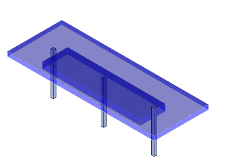
Once you have a slab you can apply Support Lines and Design Strips to your model. Design Strips are used to design reinforcement for slabs. If a design strip is drawn over various slab thicknesses, each design cut within the design strip will use the thinnest thickness that particular cut intersects. Here we will discuss the drawing of Design Strips and talk about design strip rules.
The first step in getting reinforcement design for an elevated slab floor is defining design strip rules. To define design strip rules, click the Slab Design Rules button on the Data Entry toolbar.
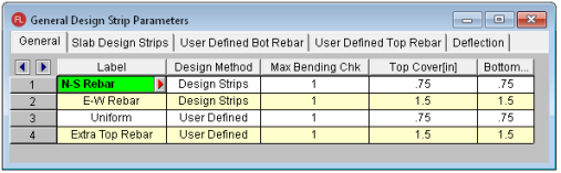
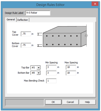
Setting a Max Bending Check value controls the rebar which the program chooses for the slab design. A value of 1.0 denotes that the program may choose a rebar layout that is at 100% of capacity. To build in extra safety a value < 1.0 may be used.
This is used to define the cover to the outer-most bars in the slab. The default N-S and E-W rules are slightly offset to account for the overlapping nature of the bars in a two-way slab. You should adjust the cover to reflect the specific bar size selected.
There are two methods available; Design Strips or User Defined. Design Strips use the traditional methods that use Column/Middle Strips and the User Defined allows the user to define a uniform rebar.
The Top Bar and Bottom Bar columns define the reinforcement bar sizes that are to be used. You may specify your rebar set in the Model Settings - Design.
Deformed welded wire sizes can be selected from the Top Bar and Bottom Bar drop down list when enabled in the Model Settings - Design.
The Max Top Bar Spacing, Min Top Bar Spacing, Max Bot Bar Spacing, and Min Bot Bar Spacing columns are used to set the maximum and minimum bar spacing for the slab reinforcement. The units are listed in the column headers.
The Spacing Increment column sets the rebar spacing increment that will be used by when analyzing various rebar layouts between the maximum and minimum bar spacing set in the previous columns. The units are listed in the column header.
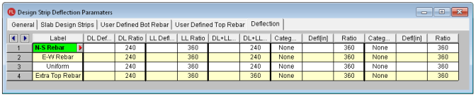
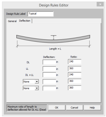
The deflection is calculated based on the span length measured along the support line from face of support to face of support.
For further information see the Deflection Results Spreadsheet.
Enter the maximum allowable dead load deflection and/or the minimum dead load deflection to slab span length ratio.
Enter the maximum live load deflection and/or the minimum live load deflection to slab span length ratio.
Enter the maximum dead + live load deflection and/or the minimum dead + live load deflection ratio.
The remaining columns allow you to set deflection criteria for other load categories. Enter the category, the maximum deflection and/or the minimum deflection ratio.
Note:
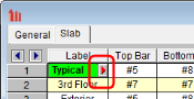
Pressing the red arrow in the Label column will open the Design Rules Editor, where the spreadsheet information can be edited with an intuitive dialog.
The General tab is used to enter all the cover spacing, bar size and spacing range, and maximum bending check.
Deformed welded wire sizes can be selected from the Top Bar and Bottom Bar drop down list when enabled in the Model Settings - Design.
The Deflection tab is used to set the deflection limits and ratio.
Below is a road map to all the Design Strip terms used in the program. There are a variety of Plot Option settings as well as toolbar buttons to turn on and off the hatch and labeling. Refer to the Model Display Options - Design Strips/Cuts for more information.
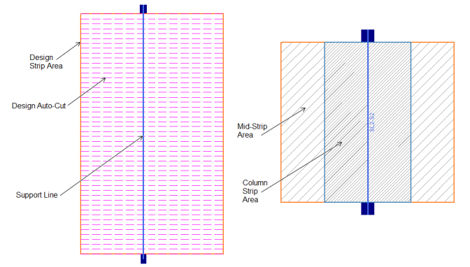
SL is the default prefix for Support Lines. You can adjust the prefix in the Slab Design Strips spreadsheet.
S indicates the Span and each span will be assigned a number starting at the first point the Support Line was created.
Once Slab Design Rules are defined then the Support Lines and Design Strips are drawn. The first step is defining Support Lines in the model.
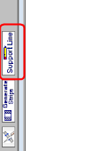
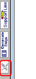
To define Support Lines for your model press the Support Line button:
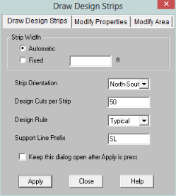
The Automatic option will automatically (at solution or after pressing the Generate Strips button  ) define a strip width that extends to a slab edge or a parallel design strip. The Fixed option allows you define the exact width of the Design Strip.
After making modifications to the slab edge or surrounding Design Strip areas, you can click the Generate Strips button to re-draw the extents of the Design Strip areas. If the Design Strip has been modified it's width will not be over-written and it will be drawn in purple to indicate it's modified.
The Strip Orientation, Design Cuts per Strip and Design Rule entries are explained further in the Slab Design Strips spreadsheet.
Once these items are selected, press Apply and we are ready to draw Support Lines.
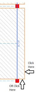
In the example below we will start with East-West Support Lines and click on the columns as our supports. For the first Support Line we will click on the column at Grid E1 and then click the column at Grid E7.
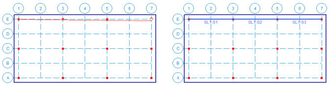
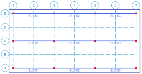
Here we see that we get a single Support Line (SL1) with multiple spans (S1-S3). We continue by drawing the rest of the Support Lines in the East-West direction.
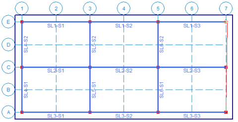
From here edit the Draw Design Strip dialog to draw the North-South strips.
Note: You can draw a Support Line to a non-support point to create spans that don't end on support points. However, the results are based on the assumption that the span is defined from support point to support point.
After all Support Lines are drawn then the program will automatically draw the Design Strip widths by either solving or pressing . Once this is done the strips are shown graphically. In the image below, the width of the strip is outlined in orange. If the Strips and Support Lines are drawn correctly, the design results can be reviewed after solution. See the Elevated Slab - Design Strip Results topic for more information.
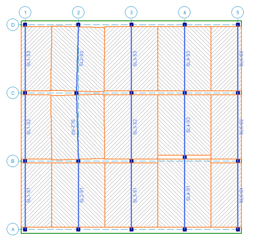
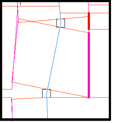
The automation of the Design Strip width is calculated based on half the distance from the Support Line to the neighboring Support Line. Neighboring Support Lines must be the same direction (N-S or E-W). Below shows a simple example of how this is calculated.
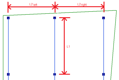
L1 = Span along the Support Line from support to support.
L2 = Span from the Support Line to neighboring Support Line (left and right).
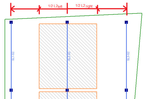
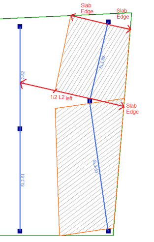
If the Support Line is at an edge and there is no adjacent Support Line then the Design Strip will extend to the slab edge.
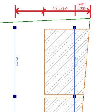
The slab edge and the Support Line distance can both vary along the distance of the Support Line. To solve this scenario, the program will find two widths for the start of the Support Line and the end. These two widths will be connected to form the Design Strip.
From here we can modify these slab edges, edit/add Support Lines, etc., from the other tabs of the Draw Design Strip dialog.
To modify Design Strips click  and click on the Modify Properties tab.
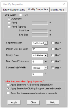
This allows you to edit the Strip Width, Strip Orientation, Number of Design Cuts per Span, Design Rule and Drop Panel. Check the appropriate Use? checkboxes, press Apply and click on individual Support Line.
This allows you to edit the Column Strip thickness by adding a Drop Panel. The Drop Panel Thickness is the additional thickness below the surrounded slab. For example, the Slab Definitions spreadsheet defines the slab thickness of 12" and the Drop Panel Thickness is applied as 6" then the Column Strip thickness will be changed to 18". To thicken the slab beyond the column strip, see Thickened Slabs.
Once a Drop Panel is applied to the Design Strip- the Column Strip will graphically change colors to indicate the Drop Panel has been applied. Only the thickness of the Column Strip is affected by the Drop Panel, the middle strip remain the thickness of the surrounding slab. The Drop Panel will adjust the thickness for the entire support line.
Drop Panels are used to reduce the amount of negative moment reinforcement per ACI. The depth of the drop panel must project below the slab at least 1/4 of the surrounding slab thickness. The drop panel columns strip is thickened for design of reinforcement and the (FEA) plate mesh is also thickened. When the slab floor is designated as a Semi-Rigid diaphragm- the drop panel will thicken the plate mesh in RISA-3D also.
Drop Panels will affect the punching shear calculations if the shear perimeter is entirely within the drop panel. In cases where there is ever multiple thicknesses for a shear perimeter- the program will use the thinnest thickness.
Note:
The slab thickness can also be altered using Thickened Regions.
This allows you to edit the Column Strip width manually. The program will automatically calculate the Column Strip width based on the ACI code provisions, see Column Strip Width Calculation for full calculation details. However, this manual entry will allow you to override this ACI calculated value with your own width.
Note: When the Column Strip is defined manually the entire design strip will be modified. The ACI calculated column strip widths are automatically adjusted per span.
There are additional options to edit and refine Design Strips.
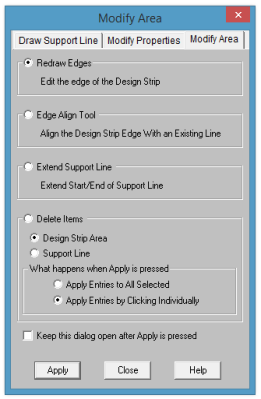
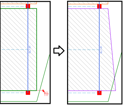
After making any modifications to the Design Strip area, the outside edges will turn purple to indicate they have been modified. If you can click the Generate Strips button, the modified Design Strips will not be affected and the surrounding Design Strips will re-generate. If you intend to go back to the original Design Strip area, you can delete the Design Strip area and then click Generate Strips again.
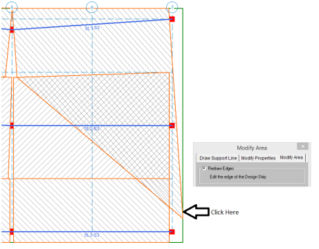
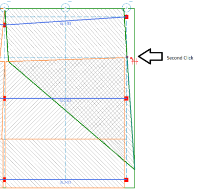
With this tool click on the edge of a Design Strip and you can then pull it out in a perpendicular direction to re-draw it.
Click on the either edge closest to the corner of the Design Strip area.
The Design Strip area edges will turn green and you can then drag the mouse closer or away from the Support Line perpendicularly. Left-click at the new location for the Design Strip corner. The Design Strip will turn purple indicating it's been modified.
There is a minimum width of 6" from the Support Line in which the Redraw tool will not allow you to draw the Support Line smaller than that minimum.
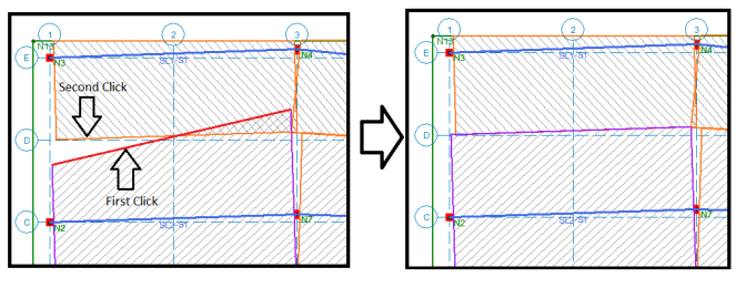
With this tool you can click on the edge of a Design Strip and then click on a slab edge to align the Design Strip edge with the deck edge.
Example 1: You can align two edges using this tool by clicking first on the edge you move, and second click on the edge to align to.
Example 2: You can align edges to any other edge in the model including non-adjacent edges.
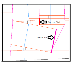
Example 3: Since the program is determining the Design Strip width based on the adjacent support line or slab edge, this example demonstrates how it may not find a perimeter nearby. This is easily corrected with the Redraw Edges tool shown below.
With this tool you can click on the end of an existing support line and drag it to lengthen it. This is a good tool to add cantilever spans to an existing support line.
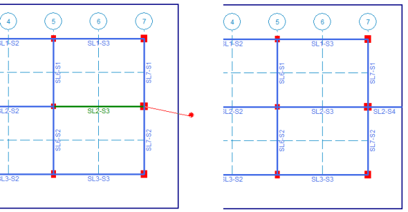
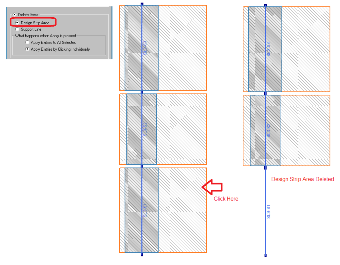
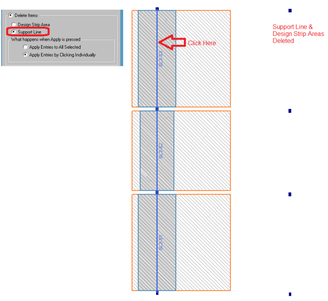
This tool can be used to delete specific Design Strips or Support Lines. You can delete the individual items or selected items.
Example 1: Delete Strip Area
This allows you to delete an individual Design Strip Area when you select "Apply Entries by Clicking Individually". This can be helpful when you've altered the Design Strip area and you want to the program to go back to the original geometry.
Example 2: Delete Support Line
This will delete the entire Support Line AND the associated Design Strip areas. The Support Line cannot be deleted in segments so if you want to delete a section, you will need to delete the entire Support Line and re-draw it in separate segments.
You can also use the Delete Items tool from the Graphic Editing toolbar to delete the Support Lines and Design Strip areas.
The Slab Design Strips spreadsheet records all design strip support lines on each floor and may be accessed by selecting Slab Design Strips on the Data Entry toolbar.
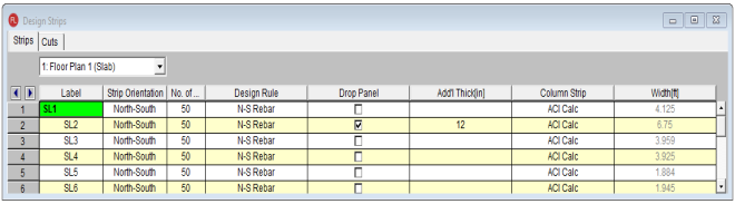
The North-South and East-West option allows you to define two separate sets of design strips for two orthogonal directions in the slab. The two main functions of this option:
A Design Strip is a collection of individual Design Cuts through the width of the strip. Each strip has the design forces calculated to produce a shear and moment diagram for the strip. This setting defines how many cuts make up the Design Strip. The larger the number of strips the more accurate the results.
Note:
The design rule defines reinforcing, deflection, cover and unity check design information for the strip. See the Design Strip Rule section for more information.
The Drop Panel checkbox will add a thickened column strip region. The Add'l Thick column is the thickness below the surrounding slab. SeeDrop Panels section for more information.
The Column Strip defines whether the program automatically calculates the Column Strip Width based on the ACI code parameters or if you Manually enter the width. See Column Strip Width for the full details of the ACI calculations.
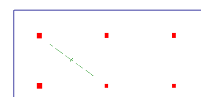
It is also possible to draw a single Design Cut in a slab to calculate forces at a specific location in a slab. This tool will not design the reinforcement; it will only provide analysis information. To do this press the manual Design Cuts button.
From here you can free draw Design Cuts on the model.
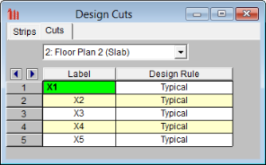
The Slab Design Cuts spreadsheet records all Design Cuts on each floor and may be accessed by selecting Slab Design Strips on the Data Entry toolbar and clicking on the Cuts tab.
Note: